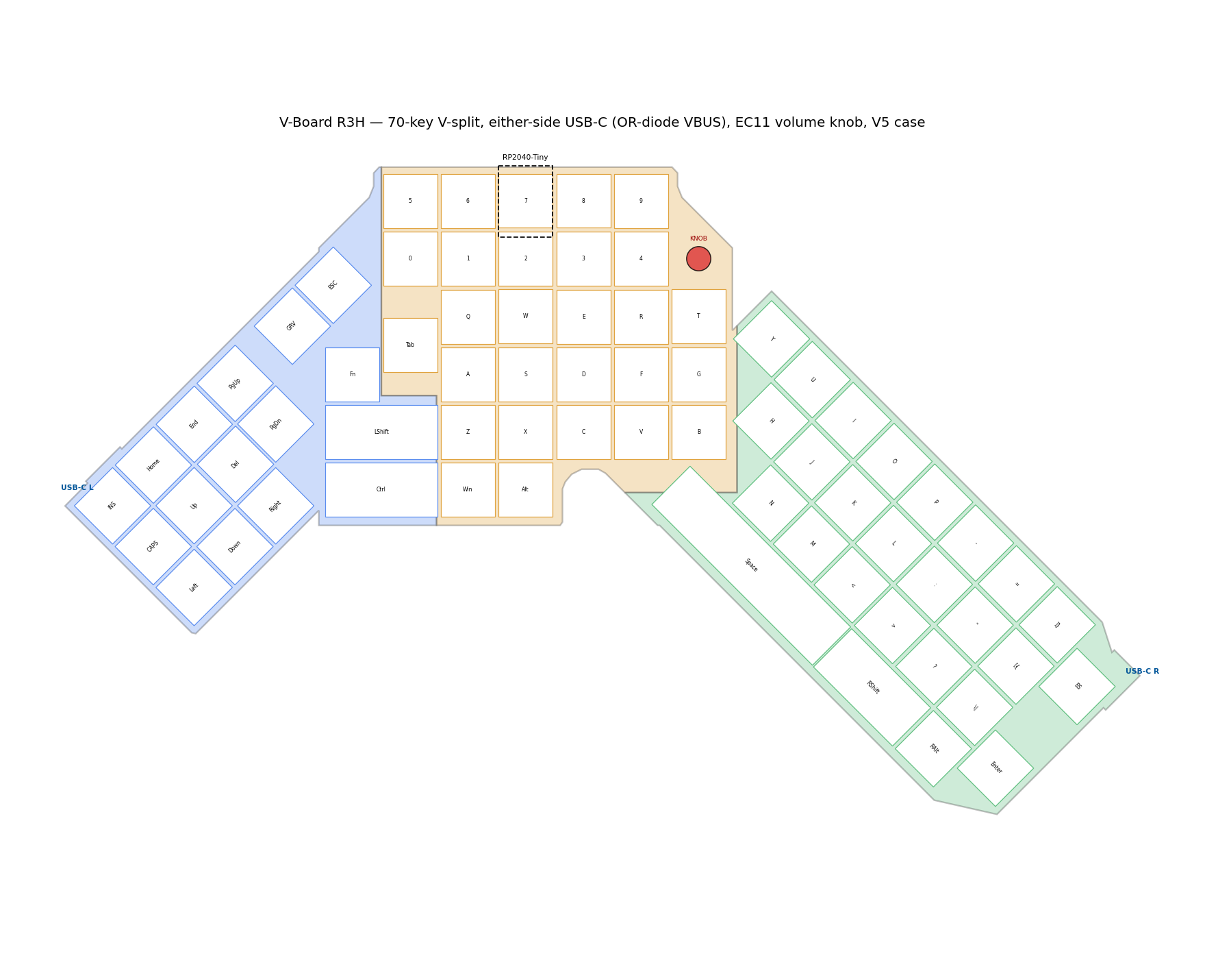
Working drawings rather than product photographs: where every key sits, what the switch plate looks like cut, what the case has to clear, and the copper on all three boards. The main page explains the design; this page shows the geometry it was drawn from.
Shading separates the three boards — left arm 16 keys, centre 28, right arm 26. The encoder sits at the end of the number row, the controller position is dashed on the centre board, and each arm tip carries a USB-C port.
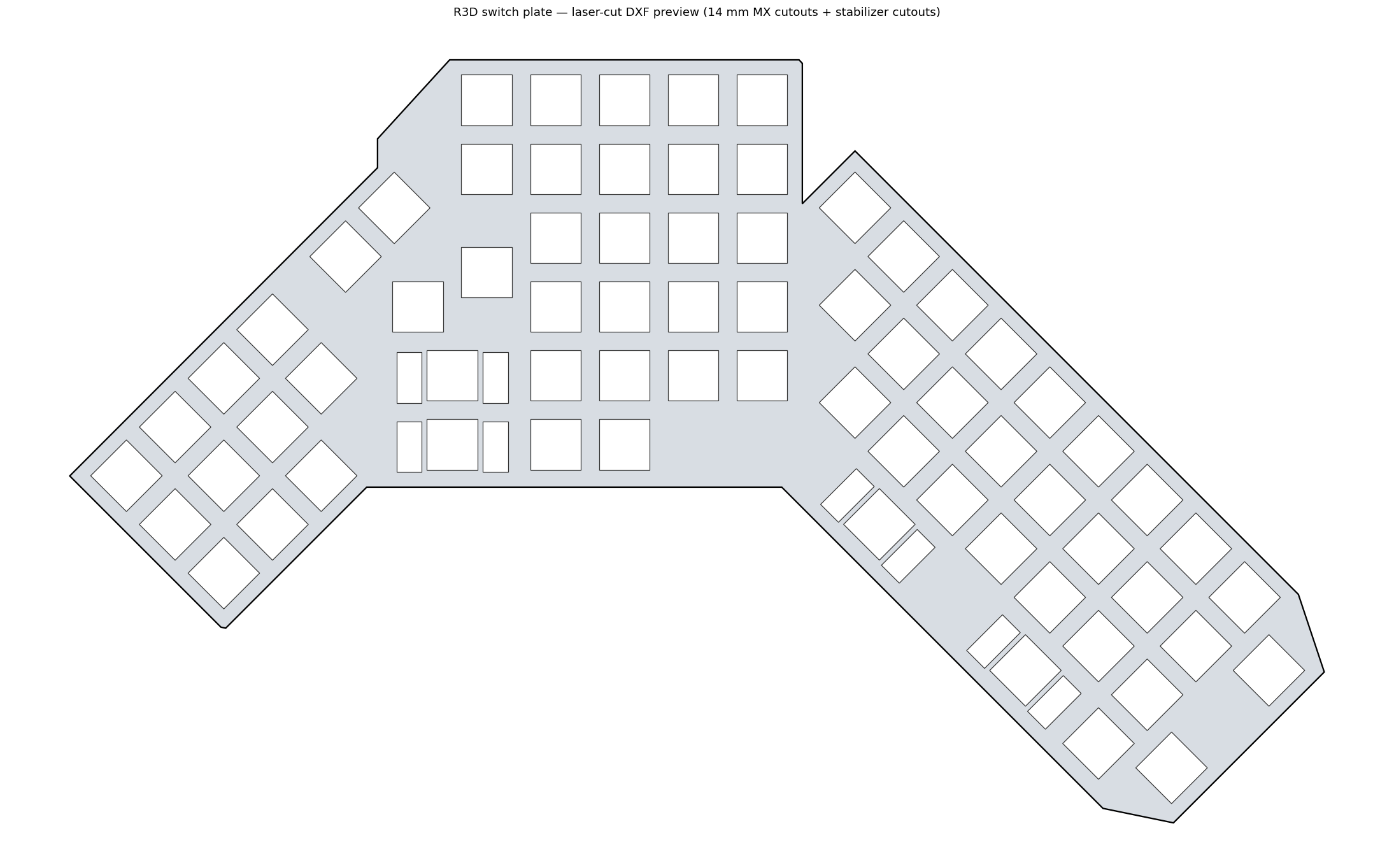
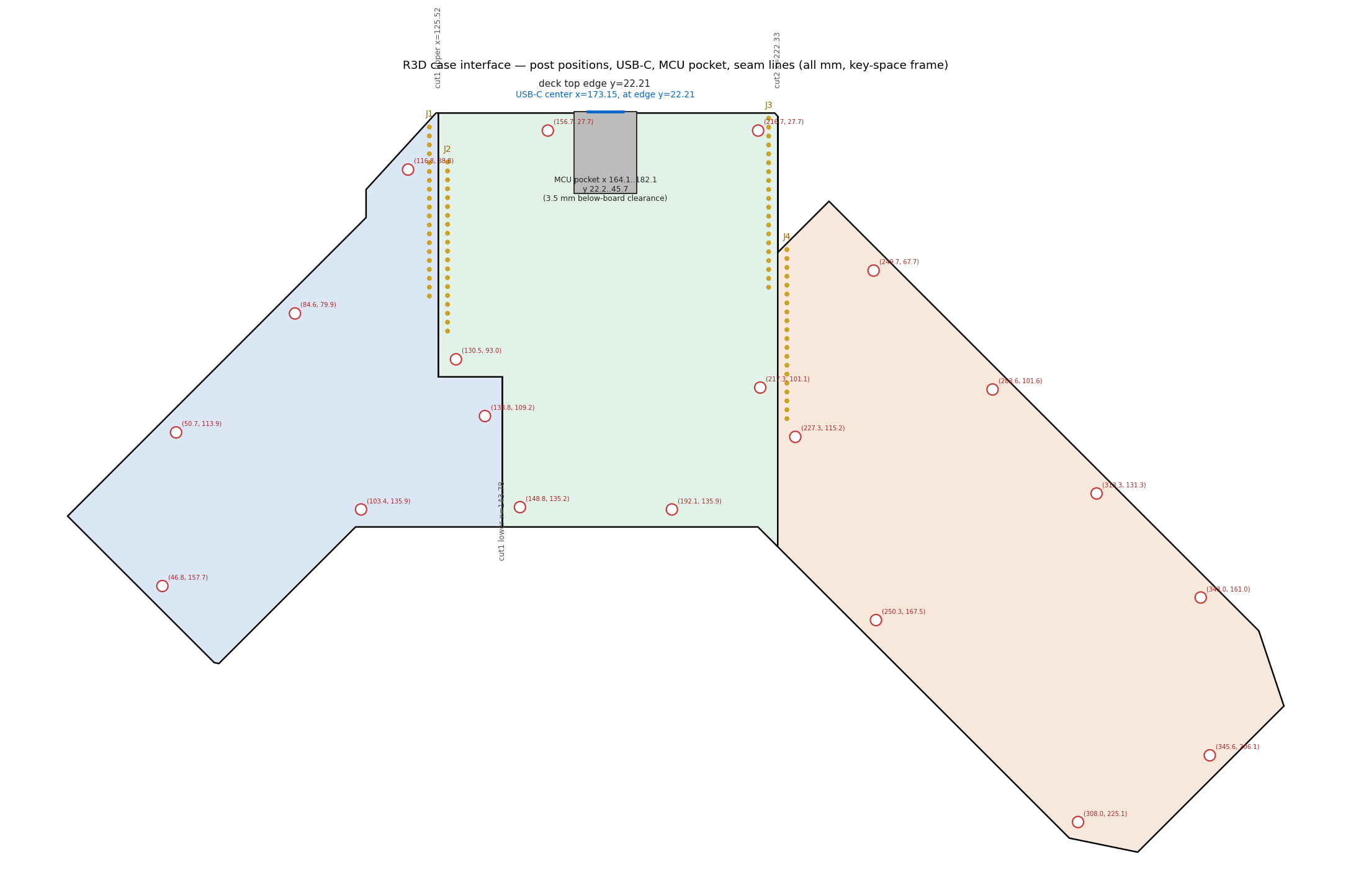
The switch plate is a single cut part carrying all seventy switch openings and the stabiliser cut-outs for the wide keys. The interface drawing maps the other half of the problem: mounting-post positions, the controller pocket, the USB-C pocket at each tip, and the seam lines where the three boards meet.


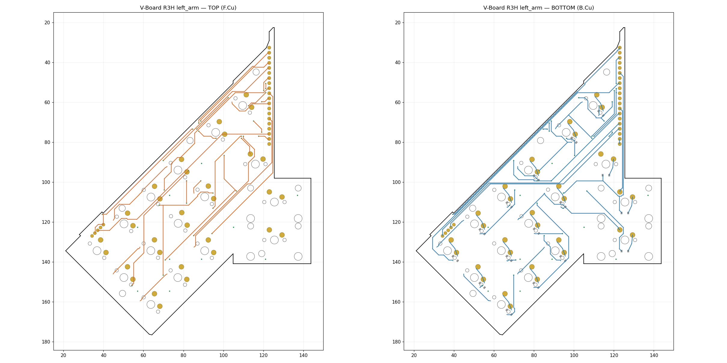
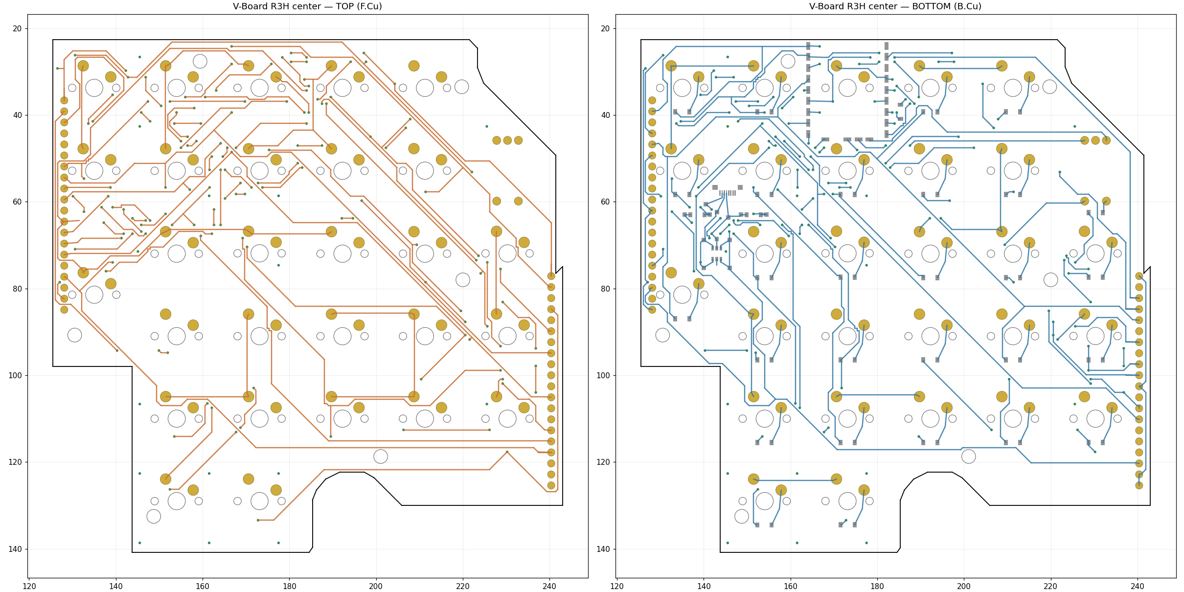
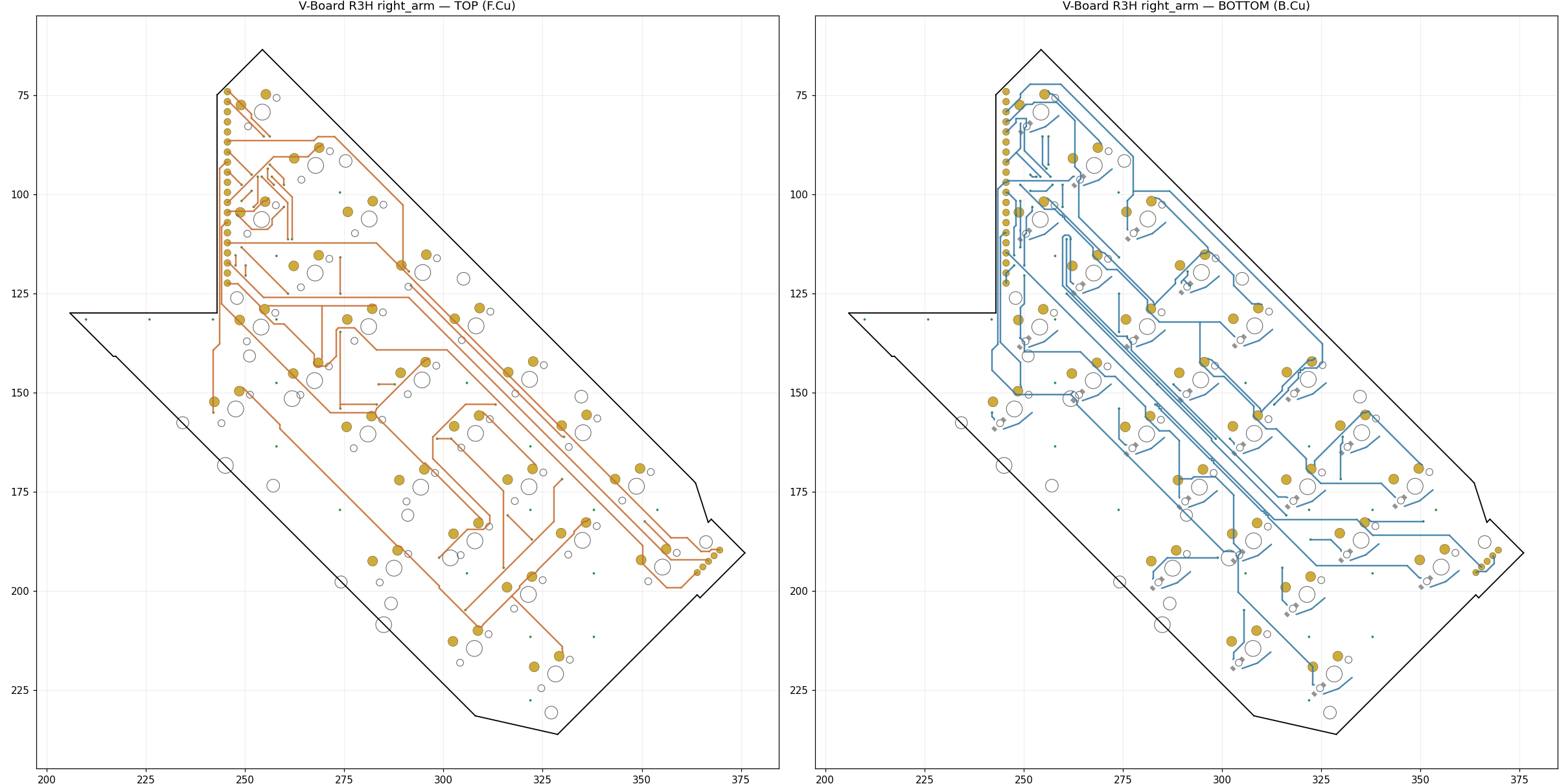
Front and back copper for each of the three boards, plotted from the fabrication files. Front copper on the left of each pair, back copper on the right; pads in gold, board outline in black. These are the plots the design rule check runs against — all three pass at zero violations and zero unconnected pads.


The layout and copper plots are current at R3H. The plate and case-interface drawings were produced earlier in the line and carry that revision’s numbering; the key positions and the 19.05 mm grid have not moved since, but treat any dimension on them as indicative rather than as the fabrication source. The fabrication files themselves — gerbers, drill, plate DXF — are the authority.